di Riccardo Raneri
riccardo.raneri@mupin.it
Questo articolo è stato scritto originariamente in lingua inglese. Per una versione tradotta automaticamente in italiano: Google Translate
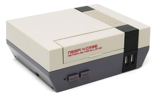 There are many Raspberry PI cases designed to give the popular single-board computer the appearance of an old game console, such as the Retroflag NESPi 4 which makes it look like a Nintendo NES from 1985. However, the idea at the base of this project is different.
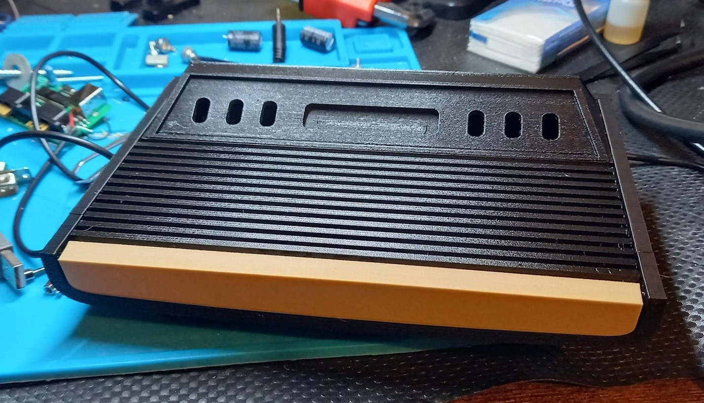
I wanted a different result: an emulator box that looks like a vintage machine, acts like it, and gives the same feelings as the original console. The game console that I chose is the Atari 2600 (also known as Atari VCS), in its original design from 1977:
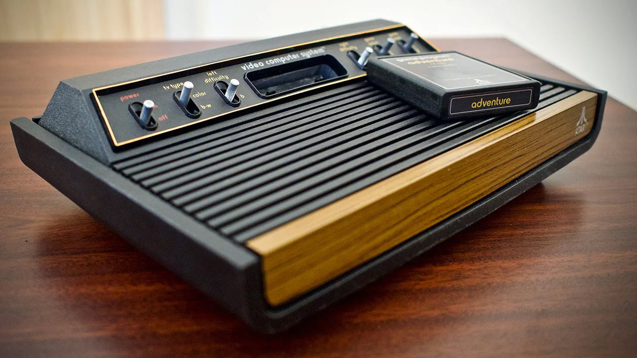
The Atari VCS “heavy sixer” – image from pcmag.com
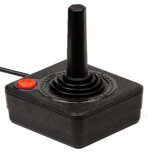
It was not only about the case: I wanted to make it compatible with the original controllers (the CX10 joystick that was in the bundle) and obtain a video output “compliant” with those years.
 The original VCS provides a composite output that is internally modulated and then sent to an antenna cable, ready to be tuned on old TVs. Many game consoles of this generation used this stratagem because old TV sets didn’t feature dedicated video inputs; televisions were used only to… watch television: no HDMI, no composite input. Just a coaxial socket to connect the antenna cable. Nobody ever liked this RF output because it is dirty, subject to interferences and it gives different results depending from many factors: the quality of the cable, the electrical environment, the type of TV…
Honestly, I didn’t want to replicate a video so full of flaws, so I chose to move to a better standard that is almost contemporary to the Atari: the SCART connector was presented in 1977 and widely adopted in Europe. It supports RGB signals and was integrated into many European TVs between the end of the 70s and the beginning of the 80s. The Atari never came with a SCART output, but it’s technically possible to modify a real VCS to obtain a RGB output, so I consider it a “respectful” choice for this project. It will give the best video you can get on a CRT TV until the 2000s, when digital outputs became mainstream.
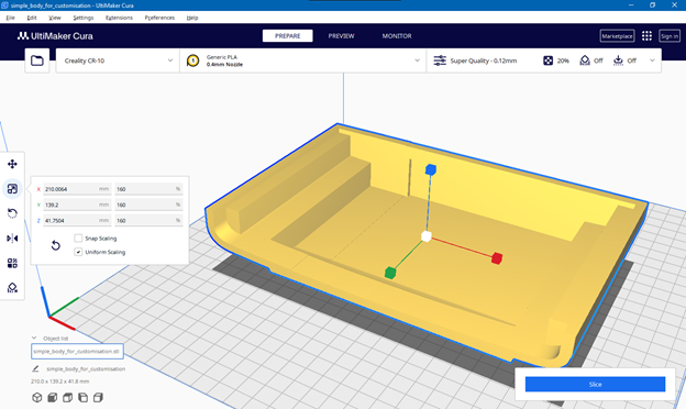
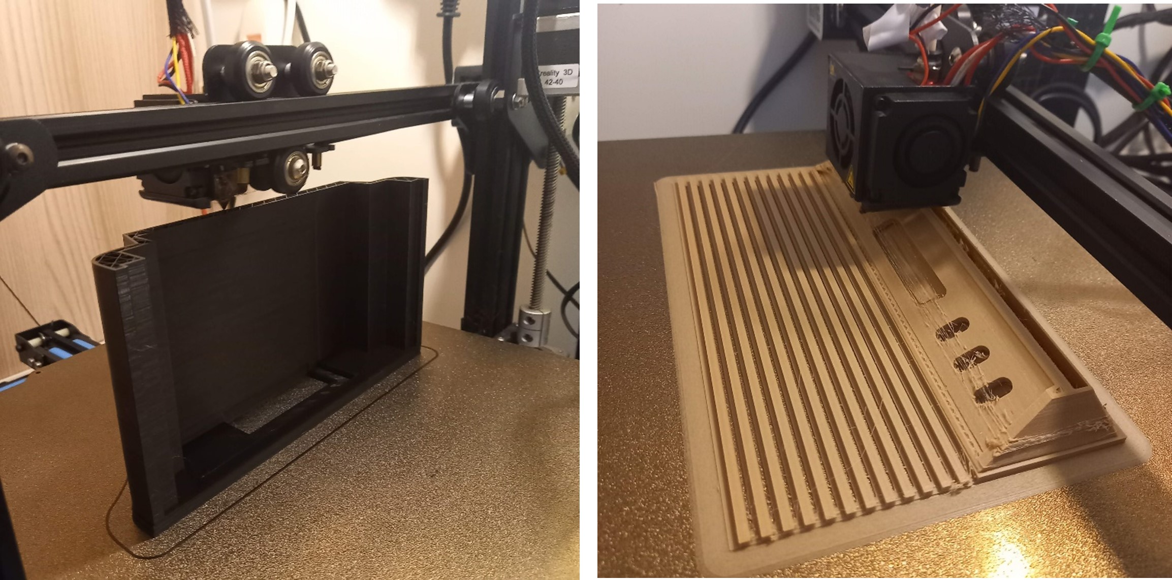
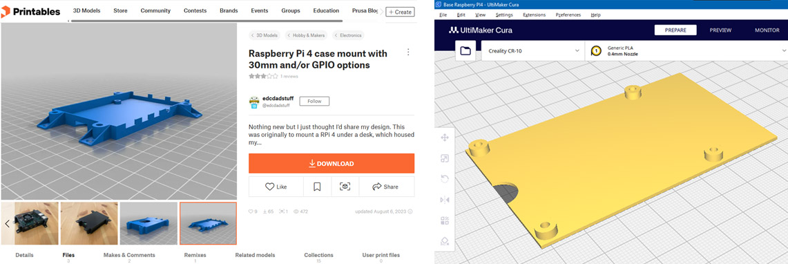
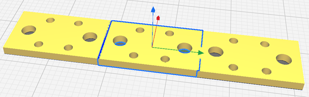
Anyway, I started with the external case. There are many free 3D models of the Atari 2600 available on the web, but most of them are too little. The best one I found is a Raspberry case on Thingiverse: that’s still a bit small for my project, but it’s very nice and accurate. Size isn’t a real issue because we can simply resize it using our slicer software (my favorite is UltiMaker Cura). I resized it by 160%, which will give me a case that is smaller than the original Atari 2600, but it will be enough to contain all the components I want to include.
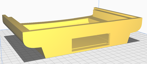
I also added a large hole in the rear panel to accomodate the SCART plug, leaving some space for the power cord as well.
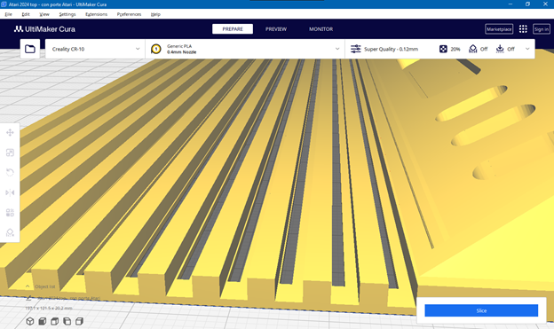
Another customization I made is a series of air inlets on the upper part. I added these holes behind the segments that form the top cover, making them “invisible” when viewed from the front.
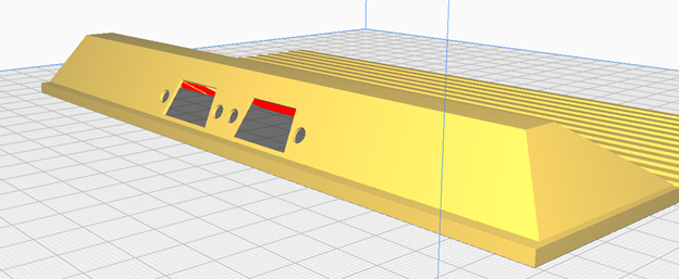
Finally, I added another two more holes behind the control panel to accomodate the ports for the Atari-compatible controllers.
Printing wasn’t without challenges, as I’ve recently been experiencing some issues with my 3D printer (a Creality CR-10 that I’ve owned for several years). It has some problems of clogging during long prints, However, I succeeded to print the pieces with sufficient quality.
Since the model doesn’t include the holes to secure the Raspberry PI 4 with screws (and even if it did, I resized the model, so the proportions are different), I downloaded another “random” Raspberry PI case model and cut it to use only the lower platform. Then I printed it and glued it to the bottom.
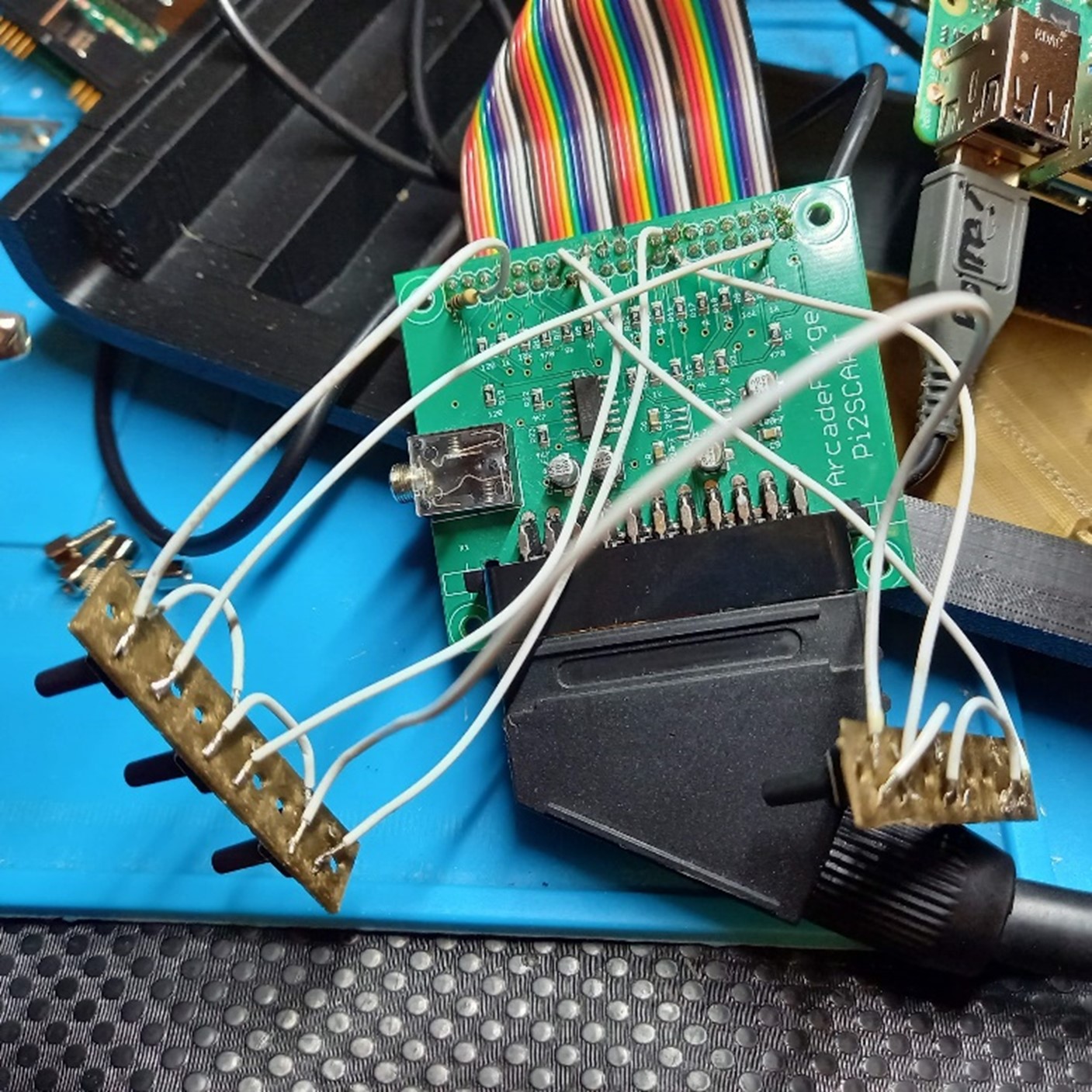
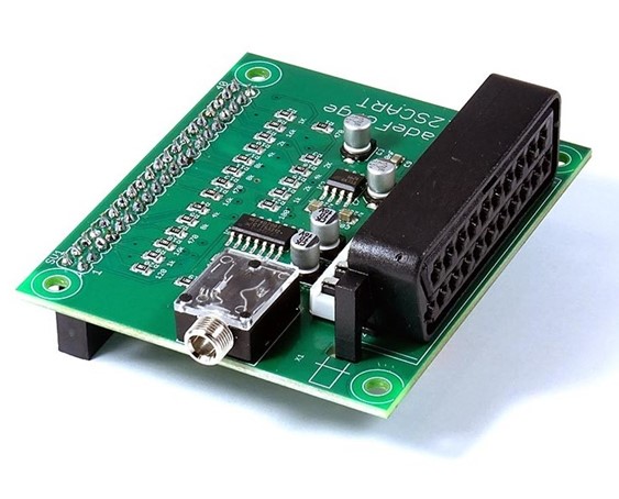 To get a native RGB output, I bought a PI2SCART, which is an “hat” compatible with Raspberry PI 3 and 4.
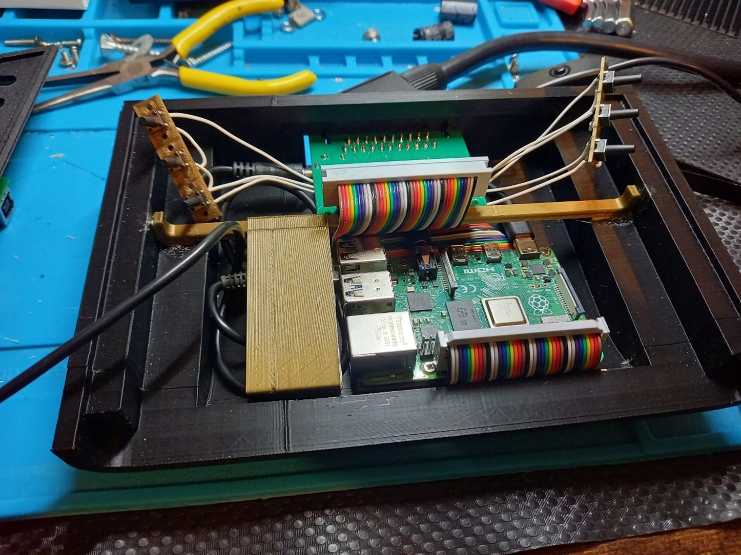
Normally, it plugs directly into the RPI GPIO interface, allowing it to sit above the board. Unfortunately, this isn’t possible here due to the limited height of the case. Additionally, I prefer not to cover the Raspberry to maximize passive cooling. So, I bought some GPIO port extenders to reposition an hat like this.

I managed to route the extension cable under the Raspberry to ensure that the upper part remains unobstructed.
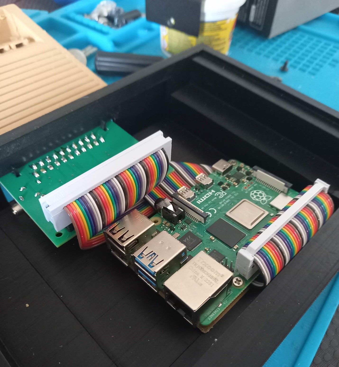
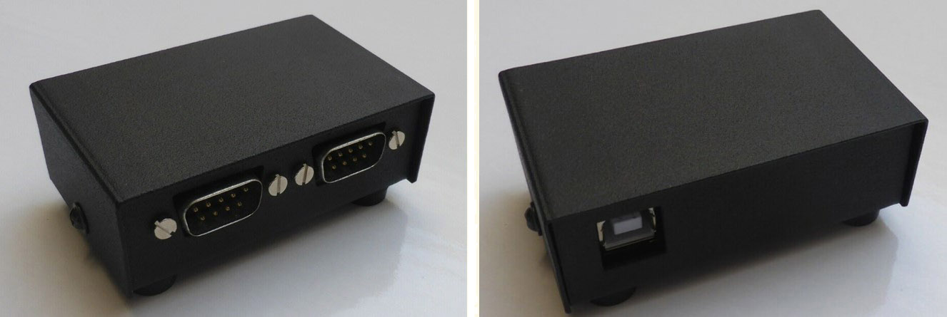
Then, the joystick ports. Some time ago, I bought a nice USB interface for this. It’s a bit costly, but it works very well.
I opened it (which is a pity, as the metallic enclosure is very nice) and mounted it on the upper part of the case where I made the holes for the ports.
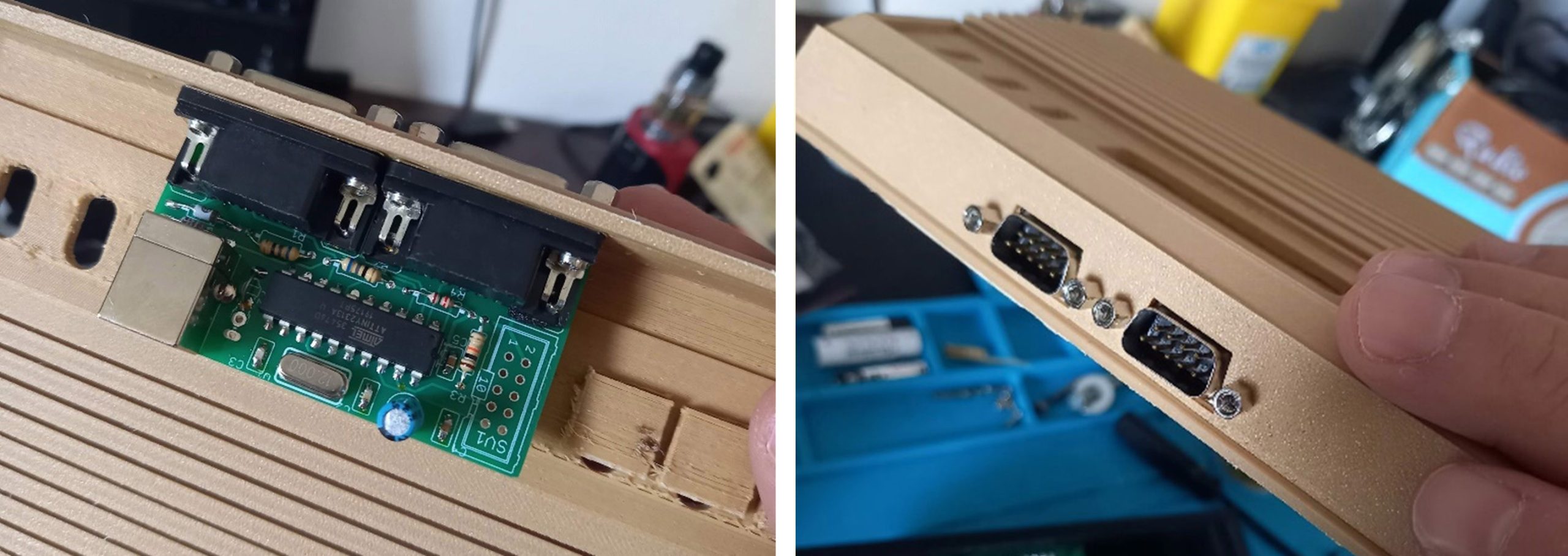
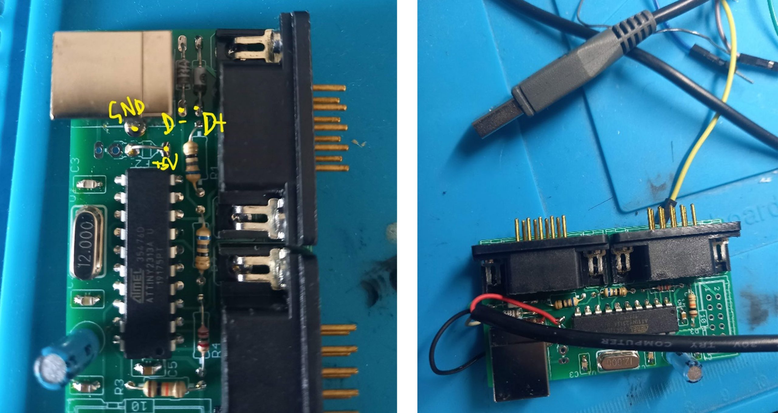
Unfortunately, the USB Type B plug is a bit cumbersome and won’t fit inside my case, so I soldered a flying USB cable directly onto the circuit.
Since I want everything to work also with these 1-button controllers, I came up with a way to add the additional commands I need:
- reset game
- select game variants
- go back to the list of games
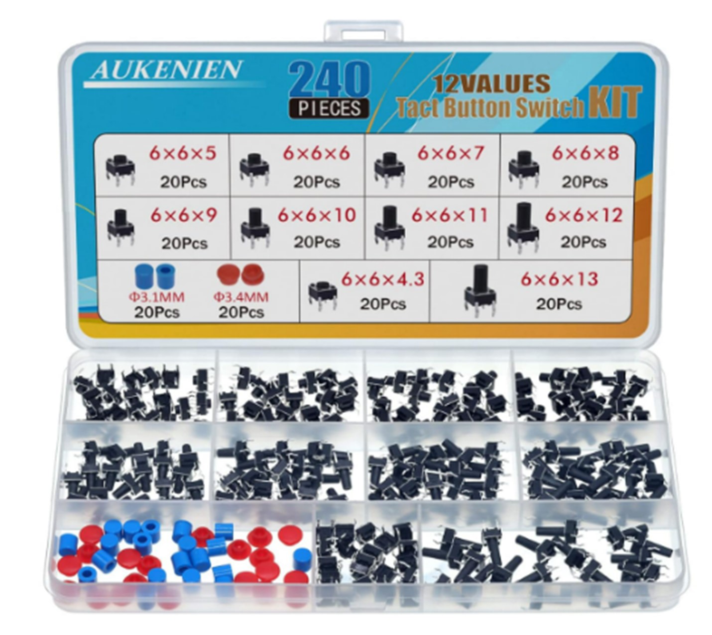 This is where the upper control panel comes into play. In the original 3D model, the 6 switches are simply decorative. I considered printing the switches and make them work mounting a push button beneath each one, but since I’m not very skilled in 3D modeling (or assembly), I opted for a simpler approach: I bought some push buttons for printed circuits and used longer ones that also act as “sliding” switches because they make contact even when pushed from the side. It’s not exactly like the original, but it’s better than a simple button.
To hold them in place, I downloaded a button mount to be printed in 3D and duplicated it to create a series of 3 mounts in row. Then I printed it twice.
The buttons will connect the 3.3V line of the Raspberry to various GPIO pins, to send keystrokes.
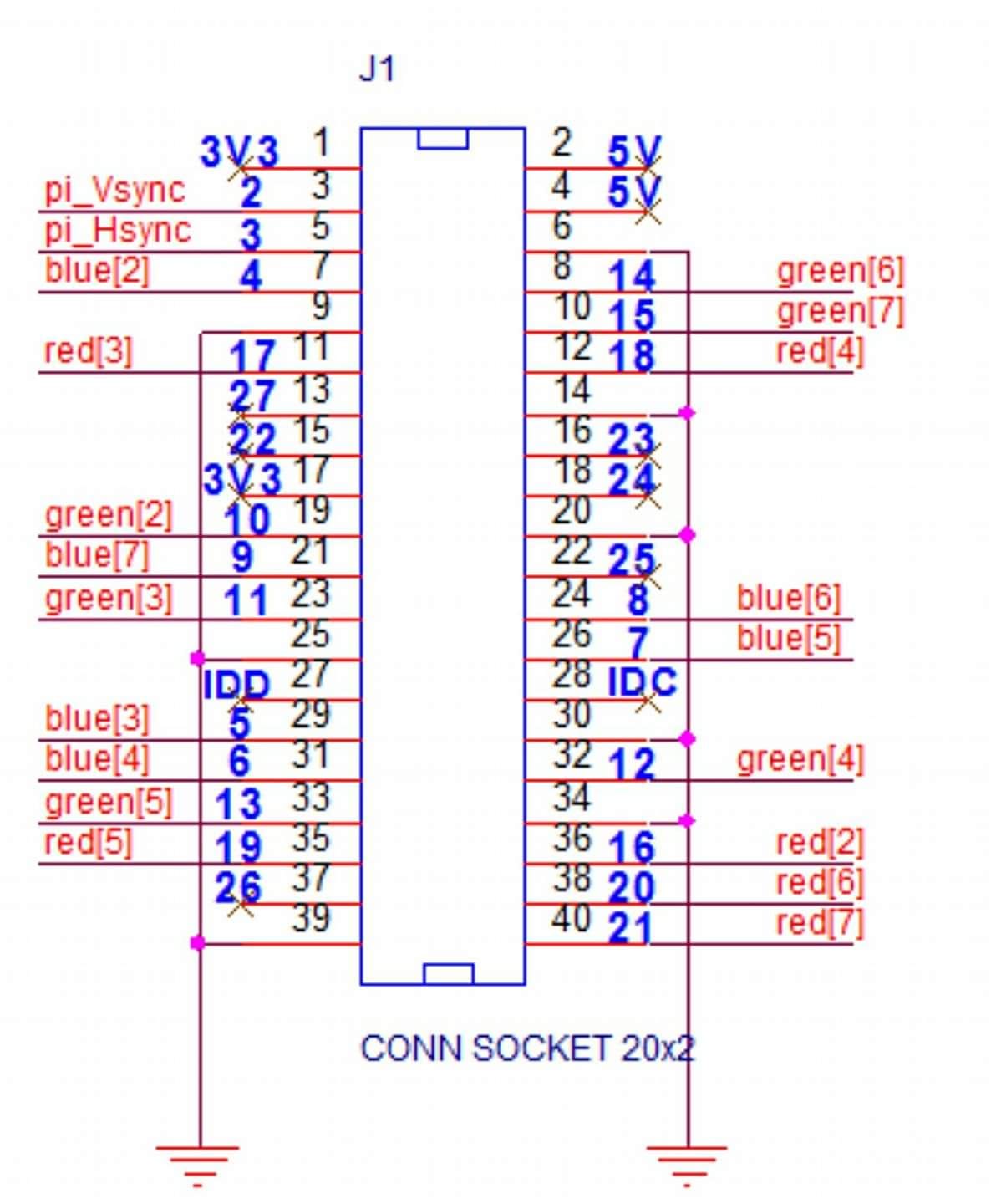 The challenge was finding free GPIOs because the PI2SCART hat uses several lines. Fortunately, I found a pinout diagram on a German forum that clearly states it’s still possible to use GPIO pins 22, 23, 24, 25, 26, and 27.
On my Raspberry PI4, however, pins 22, 25, and 27 are broken (a remnant from a previous project that didn’t go as planned…) leaving me with only 23, 24, and 26 usable. This wasn’t enough because I also wanted to add a command to put the Raspberry to sleep and another to return to the frontend, so I needed two additional working pins. The solution came from using the GPIO 0 and 1, that normally shoudn’t be used because they are reserved for HAT ID EEPROM.
I simply ignored this, and soldered my last two buttons to those pins. (spoiler: it worked).
I soldered a 1K resistor on the 3.3V pin and wired this line on the button array. Then I soldered pins 0, 1, 23, 24, and 26 to the individual push buttons. As you may have noticed, I have six “switches” on the control panel, but only 5 wired buttons. This was the best I could do with the available pins: so one button remains unused… “for future use”.
Finally, I secured the two button arrays behind the switch holes using hot glue.
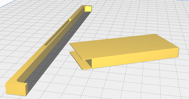
I completed the case setup with a couple of support pieces: a bar to hold the SCART socket when I insert the plug, and a “bumper” to secure this structure, since it is simply glued to the base of the case. The bumper adds extra stability, as the bar is quite thin and could otherwise bend too much.
That covers everything about the hardware. For the software, I chose Recalbox which is one of the most popular Raspberry PI distributions for retrogaming. I preferred it over Retropie, which is probably the “main” distro, because Recalbox includes support for PI2SCART out-of-the-box: you can simply activate it into the options menu.
I won’t go into detail about the entire process of installing and configuring Recalbox, as there are plenty of guides and tutorial available on this topic. However, the specific configurations I made to work with this setup were:
edit /boot/recalbox-user-config.txt
don’t forget to mount the filesystem in read/write mode if you’re editing via SSH:
mount -o remount,rw /boot
You have to add the configuration for the “GPIO keyboard”. In my case is:
# select (right shift)
dtoverlay=gpio-key,gpio=26,active_low=0,gpio_pull=down,keycode=54

# start (enter)
dtoverlay=gpio-key,gpio=23,active_low=0,gpio_pull=down,keycode=28

# esc (esc)
dtoverlay=gpio-key,gpio=1,active_low=0,gpio_pull=down,keycode=1

# back (s)
dtoverlay=gpio-key,gpio=0,active_low=0,gpio_pull=down,keycode=31
edit recalbox.conf
Here, you enable Raspberry shutdown through GPIO by uncommenting this line:
system.power.switch=PIN56PUSH
This function relies on a script located at /recalbox/scripts/rpi-pin56-power.py that normally uses GPIO3 to receive the shutdown command. Unfortunately, this pin is in use by PI2SCART, so we need to modify the script to use GPIO24 instead. This is the relevant part:
GPIO.setup(24, GPIO.IN, pull_up_down=GPIO.PUD_DOWN)
def shutdown():
  os.system("shutdown -h now")
try:
  if mode == "onoff" :
    GPIO.wait_for_edge(24, GPIO.RISING)
    shutdown()
  elif mode == "push":
    GPIO.wait_for_edge(24, GPIO.FALLING)
Again, mount the filesystem in read/write mode before editing the file:
mount -o remount,rw /
edit /recalbox/share/roms/.retroarch.cfg
We need to specify which keyboard button we want to assign to two functions that we will use:
input_enable_hotkey = "rshift"
input_exit_emulator = "escape"
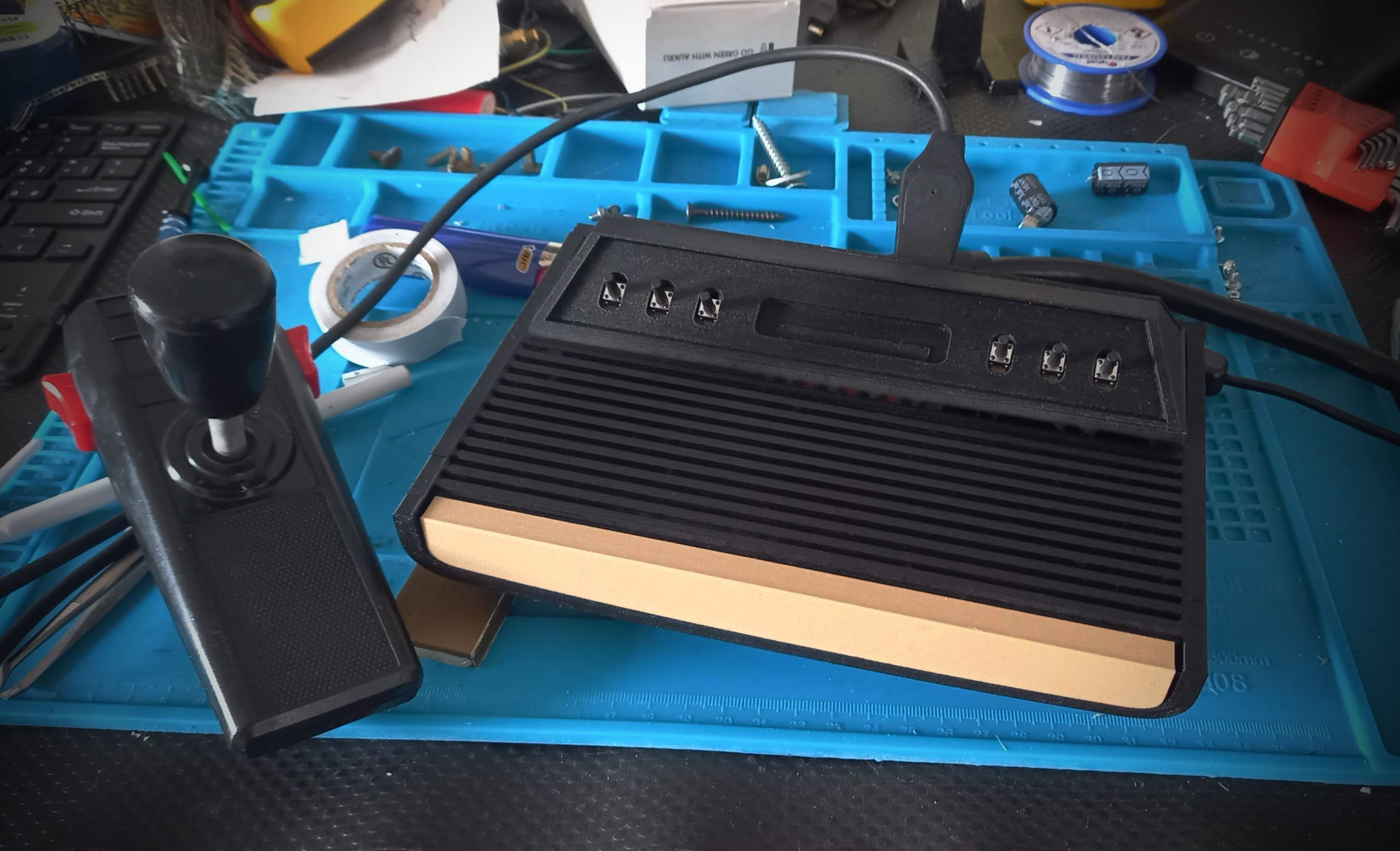
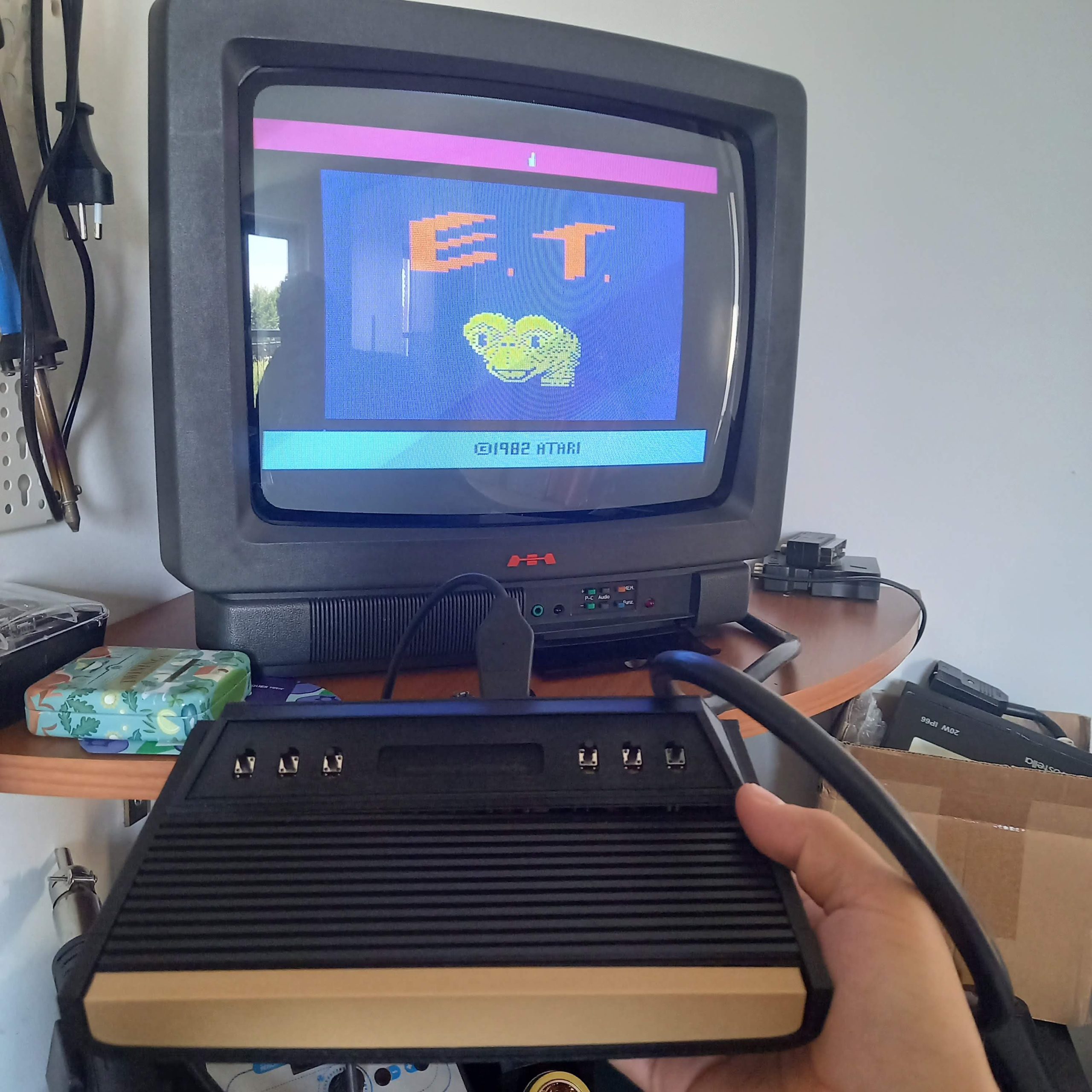
After a reboot (and after the upload of some Atari 2600 ROMs in our SD card) we are ready to play with our Atari 2024!
The control panel is mapped as follows:
- switch 1: power off (to turn it back on, you need to unplug the power adapter because we’re not using the standard GPIO3 that can wake up the Raspberry. I bought a USB cable with an on/off switch to make this more convenient)
- switch 2: unused
- switch 3: “back” in Recalbox menus
- switch 4: exit the current game
- switch 5: select (the same function as the original Atari 2600)
- switch 6: reset/start (the same function as the original Atari 2600)
Of course, we’re not limited to Atari videogames: Recalbox supports plenty of vintage systems and the Raspberry PI4 is capable of emulating even the PlayStation 1 at full speed. When it comes to systems that work well with a 1-button joystick there’s the Amiga – my favorite computer ever.
Note that in some systems (like the Amiga), switch 4 “exit game” doesn’t work (likely because the real Amiga has a keyboard, so “Esc” keystroke is interpreted as a real “Esc” key). To exit Amiga emulation, you’ll need to press the SELECT and START switches simultaneously, where SELECT acting as the hotkey and the shifted START makes the emulation end.
Now all I have to do is clean up the mess that remains on the workbench before starting a new project 🙂
